Pulse Density Modulation for software DACs
8 Mar 2011
A common method of generating an analog output signal using a digital microcontroller is to filter a pulse-width modulated digital output. A pulse-width modulator is usually implemented in hardware by having a counter run freely, with triggers set to turn off the output when the counter rolls overflows its maximum value, and turn on when the counter reaches the software-set threshold value.
Most microcontrollers have hardware built-in to do this, but when it’s not available, it can be done in software. You have an interrupt called at the same frequency as the hardware counter would have counted, implement the same logic using a threshold and a counter variable, and switch the output pin on and off accordingly. The only problem with this is the computing resources used - an 8-bit PWM would require 256 counts per PWM cycle. If you were to produce an output signal at the modest sampling rate of 1 kHz, you’d need to handle 256,000 interrupts per second - quite a lot of work for a small microcontroller.
Fortunately, there’s a reasonably simple alternative if you don’t have PWM hardware available, there’s an alternative, called Pulse Density Modulation (PDM). It can produce comparable results to PWM in software, but with a much lower interrupt rate, and less load on the CPU.
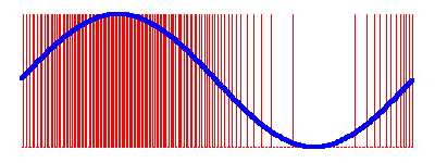
PDM is a method of continuously varying the average value of a digital signal, but without having a fixed modulation period, as in PWM. Here’s an example that shows a single cycle of a sine wave rendered as a digital signal using PDM:
How to generate a PDM output
First, we need to define a time-varying quantity called the quantization error. This is the difference between the ideal analogue output and the actual digital output:
Q(t) = D(t) - A(t)We can then define the quantization error integral, which is the sum of all the quantization errors from the first interrupt interval to the current one:
Qint(t) = integral{0, t} Q(t)PDM seeks to minimze Qint(t) at each step, or to at
least hold it within a small bounded range. A simple algorithm for this
is:
PDM-OUTPUT(input):
    error := error + input

    IF error > SIGNAL-MAX:
        error := error - SIGNAL-MAX
        RETURN 1

    RETURN 0
Here, we keep track of the current value of the integral in the
variable error. The analog signal is assumed to have a
range of [0..SIGNAL-MAX], and we keep the quantization
error to less than the maximum possible over one interrupt period.
Example: sine wave generation
In this example, we’re going to generate a sine wave on an output pin in software. First, we need a lookup table for the sine function:
/* Sine table. 256 entries representing one complete cycle. The signal
 * is scaled so that it fits the range representable with an 8-bit
 * unsigned integer.
 */
static const unsigned char sine_table[] = {
        0x80, 0x83, 0x86, 0x89, 0x8c, 0x8f, 0x92, 0x95,
        0x98, 0x9b, 0x9e, 0xa2, 0xa5, 0xa7, 0xaa, 0xad,
        0xb0, 0xb3, 0xb6, 0xb9, 0xbc, 0xbe, 0xc1, 0xc4,
        0xc6, 0xc9, 0xcb, 0xce, 0xd0, 0xd3, 0xd5, 0xd7,
        0xda, 0xdc, 0xde, 0xe0, 0xe2, 0xe4, 0xe6, 0xe8,
        0xea, 0xeb, 0xed, 0xee, 0xf0, 0xf1, 0xf3, 0xf4,
        0xf5, 0xf6, 0xf8, 0xf9, 0xfa, 0xfa, 0xfb, 0xfc,
        0xfd, 0xfd, 0xfe, 0xfe, 0xfe, 0xff, 0xff, 0xff,
        0xff, 0xff, 0xff, 0xff, 0xfe, 0xfe, 0xfe, 0xfd,
        0xfd, 0xfc, 0xfb, 0xfa, 0xfa, 0xf9, 0xf8, 0xf6,
        0xf5, 0xf4, 0xf3, 0xf1, 0xf0, 0xee, 0xed, 0xeb,
        0xea, 0xe8, 0xe6, 0xe4, 0xe2, 0xe0, 0xde, 0xdc,
        0xda, 0xd7, 0xd5, 0xd3, 0xd0, 0xce, 0xcb, 0xc9,
        0xc6, 0xc4, 0xc1, 0xbe, 0xbc, 0xb9, 0xb6, 0xb3,
        0xb0, 0xad, 0xaa, 0xa7, 0xa5, 0xa2, 0x9e, 0x9b,
        0x98, 0x95, 0x92, 0x8f, 0x8c, 0x89, 0x86, 0x83,
        0x80, 0x7c, 0x79, 0x76, 0x73, 0x70, 0x6d, 0x6a,
        0x67, 0x64, 0x61, 0x5d, 0x5a, 0x58, 0x55, 0x52,
        0x4f, 0x4c, 0x49, 0x46, 0x43, 0x41, 0x3e, 0x3b,
        0x39, 0x36, 0x34, 0x31, 0x2f, 0x2c, 0x2a, 0x28,
        0x25, 0x23, 0x21, 0x1f, 0x1d, 0x1b, 0x19, 0x17,
        0x15, 0x14, 0x12, 0x11, 0x0f, 0x0e, 0x0c, 0x0b,
        0x0a, 0x09, 0x07, 0x06, 0x05, 0x05, 0x04, 0x03,
        0x02, 0x02, 0x01, 0x01, 0x01, 0x00, 0x00, 0x00,
        0x00, 0x00, 0x00, 0x00, 0x01, 0x01, 0x01, 0x02,
        0x02, 0x03, 0x04, 0x05, 0x05, 0x06, 0x07, 0x09,
        0x0a, 0x0b, 0x0c, 0x0e, 0x0f, 0x11, 0x12, 0x14,
        0x15, 0x17, 0x19, 0x1b, 0x1d, 0x1f, 0x21, 0x23,
        0x25, 0x28, 0x2a, 0x2c, 0x2f, 0x31, 0x34, 0x36,
        0x39, 0x3b, 0x3e, 0x41, 0x43, 0x46, 0x49, 0x4c,
        0x4f, 0x52, 0x55, 0x58, 0x5a, 0x5d, 0x61, 0x64,
        0x67, 0x6a, 0x6d, 0x70, 0x73, 0x76, 0x79, 0x7c,
};
This table is small enough to fit into most microcontrollers’ ROMs, and is scaled and shifted to make PDM easier. The actual formula used to generate the above table is:
sine_table[i] = sin(i * 2.0 * M_PI / 256) * 127.5 + 127.5;Now we introduce a function to cyclically step through the table and
retrieve appropriate values at each interrupt period. The actual
frequency is controlled by the parameter sine_freq.
/* Output frequency:
 *
 *     f = sine_freq * INTERRUPT_RATE / 65536
 */
static unsigned int sine_freq = 1;

/* Current signal phase, as an 8.8 fixed-point table index.
 *
 *     theta = sine_phase * 2 * pi / 65536
 */
static unsigned int sine_phase = 0;

static unsigned char sine_next(void)
{
        sine_phase += sine_freq;
        sine_phase &= 0xffff;

        return sine_table[sine_phase >> 8];
}
A variable to keep track of quantization error and a dithering function are all that remains for the core of the implementation:
/* Quantization error.
 *
 * This is defined as the integral of the difference between the ideal
 * signal and the actual signal, from the start of PDM generation up
 * to this point.
 */
static unsigned int quant_error = 0;

/* Advance by one sample and return a value indicating what the current
 * output state should be.
 */
static int pdm_next(void)
{
        /* Choose the output state which minimizes the quantization
         * error.
         */
        quant_error += sine_next();
        if (quant_error >= 255) {
                quant_error -= 255;
                return 1;
        }

        return 0;
}
The function defined above, pdm_next, is called at each
interrupt period and returns a value telling us whether the output
signal should be switched on or off for this period.
Lastly, we tie it all together with the following test code for the MSP430-RF2500 experimenter board, which uses the PDM generator to sinusoidally vary the brightness of the two on-board LEDs:
#include <io.h>
#include <signal.h>

interrupt (TIMERB0_VECTOR) timerb_irq(void)
{
        unsigned char nv = P1OUT & 0xfc;

        if (pdm_next())
                nv |= 1;
        else
                nv |= 2;

        P1OUT = nv;
}

int main(void)
{
        WDTCTL = WDTPW | WDTHOLD;

        /* Run the DCO at 8 MHz */
        BCSCTL1 = CALBC1_8MHZ;
        DCOCTL = CALDCO_8MHZ;

        /* Configure Timer_B to produce a 2048 Hz interrupt. */
        TBCTL = TBSSEL_2 | ID_3 | MC_1;
        TBCCR0 = 488;
        TBCCTL0 = CCIE;

        /* Set up LED pins */
        P1OUT &= ~0x03;
        P1DIR |= 0x03;

        sine_freq = 32; /* approx 1 Hz */

        eint();
        for (;;);
}
The timerb_irq function (including its static callees,
which are inlined) compiles quite efficiently using mspgcc with
-O2. Here we show the instruction cycle counts along with
total cycle counts to get to each point in the function from the time
the interrupt is triggered:
timerb_irq:                                 ;; 6 - 6
        push    r15                         ;; 3 - 9
        push    r14                         ;; 3 - 12
        mov.b   &0x0021, r14                ;; 3 - 15
        and.b   #llo(-4), r14               ;; 2 - 17
        mov     &sine_freq, r15             ;; 3 - 20
        add     &sine_phase, r15            ;; 3 - 23
        mov     r15, &sine_phase            ;; 4 - 27
        swpb    r15                         ;; 1 - 28
        and.b   #-1,r15                     ;; 2 - 30
        mov.b   sine_table(r15), r15        ;; 3 - 33
        add     &quant_error, r15           ;; 3 - 36
        mov     r15, &quant_error           ;; 4 - 40
        cmp     #255, r15                   ;; 2 - 42
        jlo     .L2                         ;; 2 - 44
        add     #llo(-255), r15             ;; 2 - 46
        mov     r15, &quant_error           ;; 4 - 50
        mov.b   r14, r15                    ;; 1 - 51
        bis.b   #1, r15                     ;; 2 - 53
        mov.b   r15, &0x0021                ;; 4 - 57
        pop     r14                         ;; 2 - 59
        pop     r15                         ;; 2 - 61
        reti                                ;; 5 - 66
.L2:
        mov.b   r14, r15                    ;; 1 - 45
        bis.b   #2, r15                     ;; 2 - 47
        mov.b   r15, &0x0021                ;; 4 - 51
        pop     r14                         ;; 2 - 53
        pop     r15                         ;; 2 - 55
        reti                                ;; 5 - 60
When running at 8 MHz with a 2048 Hz timer interrupt, this function is called once every 3904 cycles and executes for no more than 66 cycles - a processing overhead of around 1.7%.
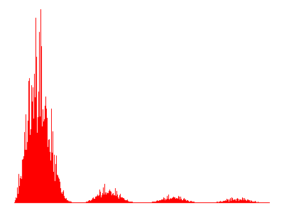
The spectrum analysis shows that the signal is probably usable for most applications which are not too sensitive to jitter. If you were to implement an 8-bit PWM in software with a function of similar complexity, all of the CPU time would be completely consumed at a sample rate of around 500 Hz.
Relationship between PDM and PWM
The concepts of PDM and PWM are not mutually exclusive. If, at each interrupt interval, you have more than two choices of output value, you can still implement PDM (just choose one of the values which minimizes the quantization error integral).
These multiple levels can be implemented using PWM, in which case you make a PDM decision each time the PWM counter overflows. If you implement your system in this way, you have dithered PWM.
Eliminate one step - by throwing away the quantization error integral, or setting it to 0 after each interval - and you’re back to regular PWM.